×

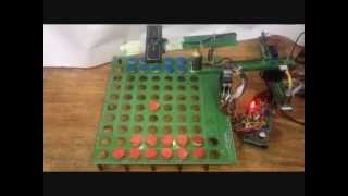
WittyRobo's video: SPrA: Spray Painting robotic Arm

@SPrA: Spray Painting robotic Arm
Project Name: SPrA S[pray] P[ainting] r[obot] A[rm] AIM: Spray painting is being done manually in factories. It is to be automated by the use of a robot. The objects to be painted are shafts. For example the propeller shaft in automobiles, which transmits the power from engine to the differential mechanism. The Spray painting automation has three subsystems: 1) Conveyer Chain and axial rotation system (already existing) 2) Robot for automation 3) Image processing to provide "Contour data" to Robot. Story + Challenges: 1) Physical dimensions of shaft may vary The shafts may be of different shape and sizes. They have can steps . They may have joints (like Universal/Omni-directional joint) so that power can be transmitted in almost any angle. 2) It is a common practice to hook multiple small shafts together, to optimize painting efforts. Usually two or three shafts may be coupled together by hooks. 3) On the conveyer chain, the shafts may appear in random order. It is not necessary that all shafts of same length comes in one batch. small, long, even multiple shafts, may come in a mixed fashion. 4) There is a conveyer chain on which all the shafts are hanged for multiple processes like: Painting the primer, drying, secondary painting, re-drying and so on till it reaches packaging zone. It moves slowly at a constant speed. Its speed cannot be changed for robotic application, the robot/other-sub systems must work accordingly. 5) When a U-joint or a step is painted, the spray gun must give more emphasis to it. The conveyer chain gives the shafts a linear motion. On the conveyer chain when the shaft reaches painting booth, a belt touches them to give them a rotatory motion along their axis. In this way the shaft can be painted from all sides with rotating the spray gun. This makes the painting easy. Instead of rotating the spray-gun the object is rotated along its axis. Prototyping: 1) A SCRA type 4-Degree of Freedom robot is developed. 2) Since the shafts can come in any order/shape/size, an image processing system provides "contour data" to the robot. For example image processing provides following data: 1) How many shafts are hanged one over the other, 2) Start and end point of each shaft, 3) Location of steps and 4) Location of Universal-Joint on each shaft 5) Additionally: If the shaft is too long or there are too many shafts 6) Additionally: If a hook is empty and has no shaft. Before developing the Robotic hardware the following Simulation: 1) Required work envelope of robot 2) Optimization of arm length: arm length v/s Work area 3) Inverse Kinematic Calculations For prototyping the object (shaft) can be configured to different shapes with varying U-joints and steps. ========== The Robot Can Work in 3 modes: 1) Complete Autonomous Mode: As shown in the video 2) Interactive Command Mode: Send command via RS-232 3) Joy-stick Mode: Move the joy-stick/rotatory-knobs and the robot moves proportionally, also shown in the video. MatlabĀ® is used for image acquisition and processing. Atmel AVR 2560 (Arduino MEGA, Quantity 2) are used.

49

1
WittyRobo
Subscribers
20.9K
Total Post
36
Total Views
1.3M
Avg. Views
36.5K
View Profile
This video was published on 2015-05-30 18:44:25 GMT by @WittyRobo on Youtube. WittyRobo has total 20.9K subscribers on Youtube and has a total of 36 video.This video has received 49 Likes which are lower than the average likes that WittyRobo gets . @WittyRobo receives an average views of 36.5K per video on Youtube.This video has received 1 comments which are lower than the average comments that WittyRobo gets . Overall the views for this video was lower than the average for the profile.

Other post by @WittyRobo