×

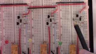
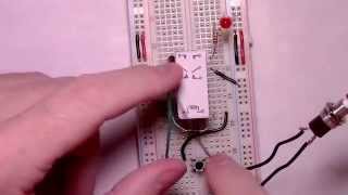
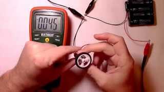
philo mech's video: Circuit Assembly Tutorials 555 Timer Monostable Mode

@Circuit Assembly Tutorials || 555 Timer, Monostable Mode
This video demonstrates how to read a circuit schematic/diagram while at the same time building a Monostable 555 Timer circuit on a breadboard. Note (!!) pin4, i.e., the reset pin, should be connected to the power rail. Such is properly represented in the circuit diagram and completed breadboard circuit shown at the beginning of the video. Unfortunately, I missed hooking it up during the step by step breadboard assembly part of the video. My apologies. One can still follow along with the video, hook everything up as shown, and then end by adding a wire between pin 4 and the power rail (VCC / +5V rail). The circuit does work without pin4 connected to VCC but it's not as stable as it would be with pin4 properly connected. Parts List: -- a 555 Timer -- 5 to 15V DC power supply (a 9V battery would be fine) -- a breadboard -- 20 to 22 gauge solid core wire or a set of standard jumper wires -- a normally open momentary button -- 100uf capacitor -- 10uf capacitor -- 0.1uf capacitors ( x 2 ) -- 10K resistor -- 100K resistor -- 330 ohm resistor -- an led For more videos like this one, various electronic, Arduino programming, tutorials, projects, and more check out and consider subscribing to my channel.

274

11
philo mech
Subscribers
7.9K
Total Post
57
Total Views
1.1M
Avg. Views
21.4K
View Profile
This video was published on 2014-08-10 06:56:08 GMT by @philo-mech on Youtube. philo mech has total 7.9K subscribers on Youtube and has a total of 57 video.This video has received 274 Likes which are higher than the average likes that philo mech gets . @philo-mech receives an average views of 21.4K per video on Youtube.This video has received 11 comments which are higher than the average comments that philo mech gets . Overall the views for this video was lower than the average for the profile.

Other post by @philo mech